Shenzhen Alu Rapid Prototype Precision Co., Ltd.
Industry News
- Home
- News
- How to calculate clamping force for injection molding?
Clamping force is the pressure applied by the injection molding machine to keep the mold halves securely closed during the injection, packing, and cooling phases. It counteracts the internal pressure from the molten plastic, preventing mold separation, flash (excess material at the parting line), or part defects. Insufficient clamping force can cause quality issues, while excessive force may damage the mold or machine. Calculating it ensures you select the right machine tonnage (typically rated in tons) and optimize production.
The standard formula is:
Clamping Force (T, in tons) = (Projected Area × Cavity Pressure × Safety Factor) / Conversion Factor
Projected Area (S): The total two-dimensional area of the part(s) and runner system projected onto the mold's parting plane (the plane where the mold halves meet). This includes all cavities for multi-cavity molds.
Cavity Pressure (P): The average pressure inside the mold cavity during injection, which depends on the plastic material, part geometry, injection speed, and mold design.
Safety Factor (K): Typically 1.1–1.5 to account for variations (e.g., 1.3 is common).
Conversion Factor: 1000 for metric units (to convert kg to tons) or 2000 for imperial (lb to tons, since 1 ton = 2000 lb).
Units
Metric (common globally): S in cm², P in kg/cm² or bar (1 bar ≈ 1 kg/cm²), T in tons (1 ton ≈ 1000 kg).
Imperial (common in the US): S in in², P in psi (lb/in²), T in tons (short tons = 2000 lb).
Step-by-Step Calculation
1.Calculate Projected Area (S):
Sketch the part and project its surfaces perpendicular to the parting line (e.g., for a rectangular part, use length × width; for complex shapes, sum the areas of all relevant faces).
Include the runner/gate area if it's a cold runner system.
For multi-cavity molds: Multiply single-cavity area by number of cavities.
Example: A part with dimensions 20 cm × 15 cm × 2 cm (projected as 20 × 15) plus a 3 cm × 1 cm runner = (300 + 3) = 303 cm².
2.Determine Cavity Pressure (P):
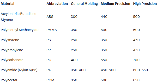
Use material-specific tables for average pressure. Higher precision molding requires higher pressure.
Factors influencing P: Material viscosity, wall thickness, flow length (longest path from gate to end of part), injection speed, and mold temperature.
If you have mold flow simulation software (e.g., CAE analysis), use the peak pressure value.
Rough estimate: Divide flow path length by thinnest wall thickness to get a ratio, then reference charts (e.g., for a 177:1 ratio and 1.5 mm wall, base P ≈ 250 bar).
Here's a table of common cavity pressures (kg/cm²) for general molding:

3.Apply the Formula:
Plug in values: T = (S × P × K) / 1000 (metric).
Select a machine with tonnage ≥ calculated T (round up to the nearest standard machine size).
4.Verify with Production Testing (Empirical Method):
Start at 70–80% of machine max tonnage.
Inject parts and measure weight/dimensions; reduce tonnage in 10-ton increments until flash appears or weight increases ~5% (indicating separation).
Optimal T is just above the failure point + 5-ton safety margin.
This refines calculations and accounts for real-world variables like venting.
Key Considerations
1.Material and Design: Thin walls or long flow paths increase P; crystalline materials (e.g., PA) need higher force than amorphous (e.g., PS).
2.Hot vs. Cold Runner: Hot runners reduce projected area (no runner pressure).
3.Machine Selection: Ensure tie-bar spacing fits mold size; over-tonnage wastes energy and risks mold deflection.
4.Safety Margin: Always add 10–20% extra; monitor with sensors (e.g., cavity pressure or deflection) for optimization.
5.Tools: Use mold flow software for accuracy; consult material suppliers for custom P values.
